- #Aem air fuel ratio gauge flashes error code 3 times install
- #Aem air fuel ratio gauge flashes error code 3 times software
- #Aem air fuel ratio gauge flashes error code 3 times Offline
- #Aem air fuel ratio gauge flashes error code 3 times professional
- #Aem air fuel ratio gauge flashes error code 3 times free
#Aem air fuel ratio gauge flashes error code 3 times software
MarkDamn :(Euro people, We really need to help Mark as much as we can as he - in my opinion - is the ONLY software tuner that will/might be able to offer us custom Siemens MSS50 software within North America. BMW ISN Reader and Writer Software BMW ISN Editor Software in Autohex II lets you read ISN from DME, match it with CAS. DME flashing and tuning software for a variety of BMW chassis and ecu models. As the whole process takes about 25 minutes to do on a reasonably fast laptop and if you have a crap battery and the voltage drops below 13.
#Aem air fuel ratio gauge flashes error code 3 times free
Free for all user: Make dealer key for CAS4 encrypt version, support add key. my mechanic told me that he will flash my dme with europe version to clear off the secondary air system causing check engine light. B58 DME's must be unlocked and bench flashed by Dinan.
#Aem air fuel ratio gauge flashes error code 3 times professional
VVDI BMW Tool is Comprehensive function Professional tool.
#Aem air fuel ratio gauge flashes error code 3 times Offline
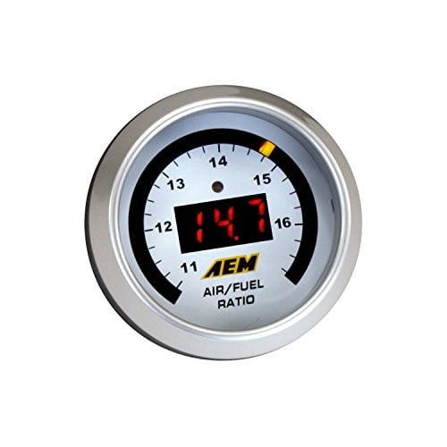
Comes with 3 different OTS Maps included, specific for your BMW! BMW B58 DME Bench Unlock - Which tool? mohamedramli Location Offline Newbie Reputation: 0. By posting the year, make, model and engine near the beginning of your help request, followed by the symptoms (no start, high idle, misfire etc. The sensor is not designed for operation on leaded fuels, doing so will dramatically shorten sensor life.Bmw dme flashing tool. Specifications Gauge Supply Current (nominal, peak) 1.3A, 2.7A peak Differential Analog Outputs 1 Measuring Range 8.5:1 to 18:1 AFR Gasoline Sensor Accuracy 0.1 AFR Operating Voltage (nominal) 8.5-15 volts dc Harness & Connector Temp Limit: 105C Notes The sensor contains a ceramic module and should not be subject to mechanical or thermal shock or it may be damaged. AEM F/IC P/N 30-1910(X) 30-1930(X) Lambda Pin Pin 18 of 22-pin connector Pin 18 of 22-pin connector Pin 20 of 20-pin connector Sensor GND Pin Pin 5 of 22-pin connector Pin 5 of 22-pin connector Table 4. Table 4 below lists the Lambda and Sensor ground pin locations for the different FIC part numbers. F/IC Aux Gauge Setup Connect the WHITE Analog Output + wire to the Aux Gauge input and the BROWN Analog Output – wire to the sensor ground. # of Flashes 1-6 Fault Sensor Wiring and/or sensor 7 System voltage below 10 volts dc Corrective Action Check sensor cable for broken wires/shorts Check electrical system for good connections and proper function Table 1. The backlight switch is accessed through the small hole in the back of the gauge. To change the backlight color, rotate the backlighting switch using a small precision style screwdriver. If you anticipate high EGT's (over 800C), run a turbocharger, run at high RPM for extended periods of time or plan on running leaded race fuel then you must mount the sensor at least 36 inches or more downstream of the exhaust port as all of these can cause the sensor to overheat.īacklighting The Analog Wideband UEGO Gauge has 7 different backlight colors available to the end user, which closely match some of the more common factory dash panels: white, blue, green, red, orange, light blue, and aqua. Mount the O2 sensor in the exhaust system at least 18 inches downstream from the exhaust port. Sensor Mounting A weld-in M18 X 1.5 boss is supplied for sensor installation. Connect the sensor to the gauge using the 6-wire sensor cable.


Note: the locating tabs on the side of the connector should be nearest the center of the gauge. Plug the 8-wire power harness into the mating connector on the back of the gauge and connect the wires as shown in Figure 1. Secure the gauge in a 2 1/16th” (52MM) mounting hole with the supplied bracket.
#Aem air fuel ratio gauge flashes error code 3 times install
Wiring Schematic AEM Gauge-Type UEGO Controller Parts 1 x 35-5130(B/W) UEGO Gauge Assembly 1 x 30-2001 UEGO Sensor 1 x 35-8535 Install Kit (O2 Bung with 6 Butt Connectors) 1 x 10-5130 Installation Instructions 1 x 35-3411 8-Pin Power Harness 1 x 35-3400 6-Pin Sensor Harness 1 x 35-8529S Silver Bezel AEM Performance Electronics th 2205 126 Street Unit A, Hawthorne, CA. Part Number 30-5130 Analog Wideband Air/Fuel Ratio Gauge Figure 1.


 0 kommentar(er)
